What happens when insurance companies decide to withdraw and no longer cover the most at-risk areas? That is the theme at the heart of the new report by the environmental NGO, but also of "Sigma", that of the Swiss Re Institute. Analysis
"Flexibility solutions are now essential. However, they face a structural difficulty: their costs are decreasing faster than market rules evolve," explains Xavier Blot, associate professor at emlyon business school.
By naming their first edition "Wind farms are taking shape", the industry's players want to show a certain optimism despite a context that remains complicated for the sector. A look by Benoist Guillard, president of the Groupe romand pour l’énergie éolienne (GREE).
A railway microgrid in the service of the energy transition?
The railway network can play an important role at a time when electrical grids must be strengthened to achieve the objectives of the 2050 Energy Strategy.
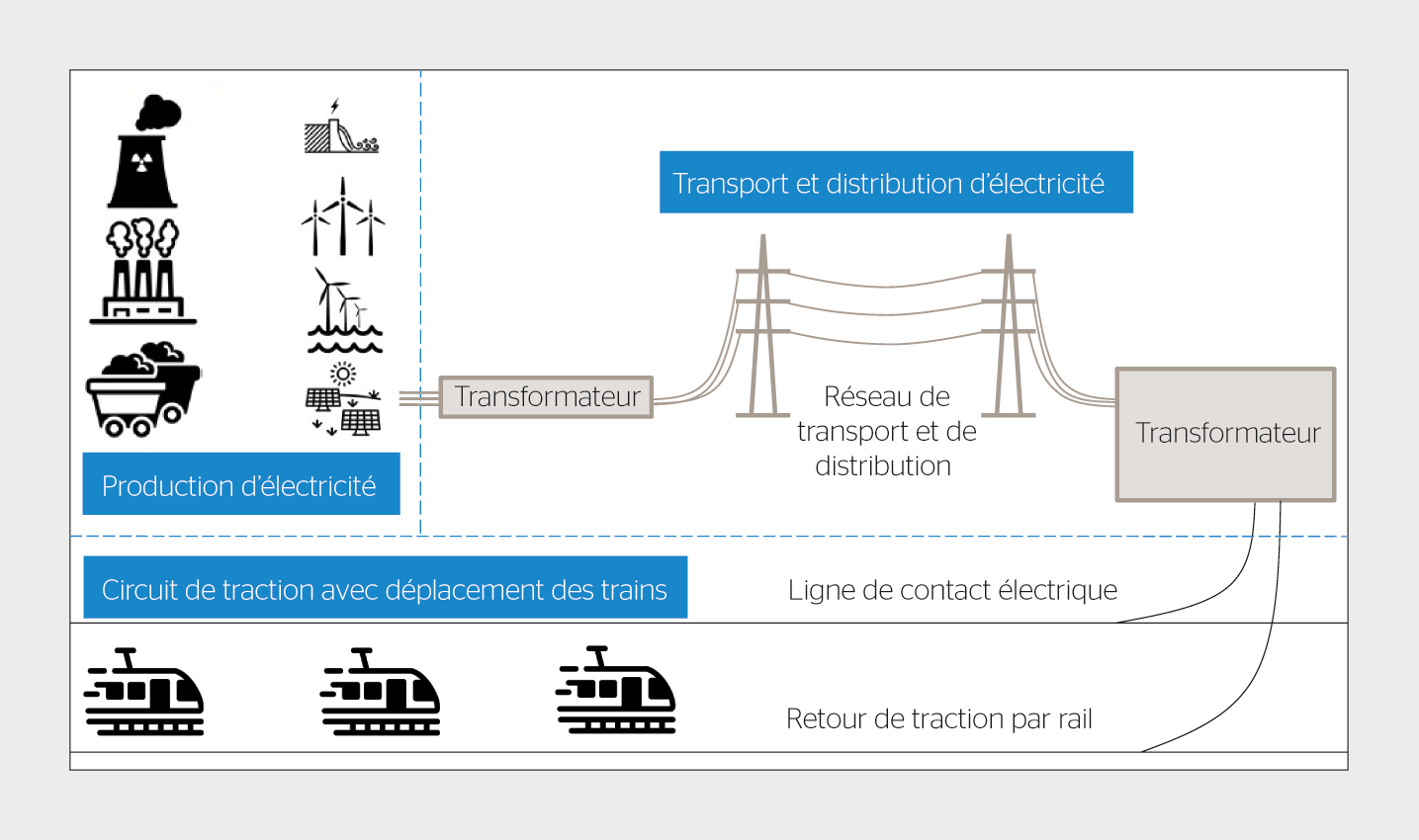
When one talks about rail transport in Switzerland, the traveller immediately thinks of the wide range of destinations, the punctuality of the trains and a means of transport with a low carbon impact. This is made possible thanks to efficient operations, rolling stock that is economical in energy and a specific electrical infrastructure. From a technical point of view, this electrical infrastructure – also called the traction circuit – is composed of transform substations, contact lines (also called catenaries), power transmission and distribution networks, as well as means of electricity production (figure 1).
Figure 1 Diagram of the railway electrical infrastructure.
This infrastructure is subject to various constraints. First, it must be able to power the trains, whose power can reach a few megawatts at the moment of acceleration: it is therefore sized to withstand the large intermittent power draws generated by rail traffic on the line. A second technical constraint is related to the movement of trains along the track, which causes a separation between the load and the energy source (substation). This elongation of the traction circuit results in an increase in electrical resistivity, which directly leads to an increase in voltage drop and induces significant voltage reductions at the train's pantograph.
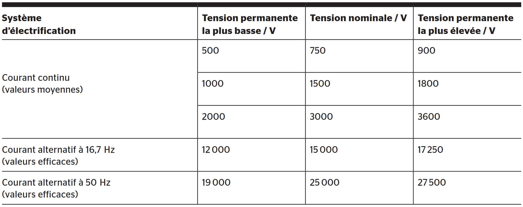
These two technical constraints have led to the development and consideration of specific electrical standards for the railway electrical network. These tolerate voltage variations on the catenary on the order of ±30% of the nominal voltage value (table 1). Compared with the ±10% variations allowed on a conventional electrical network, the railway network supports much larger power, and therefore voltage, fluctuations.
Table 1 Supply voltages of traction networks: excerpt from standard EN 50163 [1].
If we now consider the areas of railway land – including the 5200 km of tracks and the multimodal transport hubs around stations – Switzerland already has an electrical infrastructure ready to contribute to the energy transition. This article proposes using railway microgrids to enable the integration into the railway electrical network of linear photovoltaic (PV) installations as well as charging points for electric cars and buses. An application case based on a 750 V direct-current line with idle substation settings at 850 V (to meet operational constraints) was studied, which made it possible to determine, on the one hand, the energy impact of PV installations on the railway network's consumption and, on the other hand, the benefits related to the integration of charging stations for electric vehicles (EVs) near stations.
What is a railway microgrid?
A railway microgrid is defined as an extension of the railway electrical network allowing the provision of new energy services. The integration of a microgrid on railway land is based on using the catenary as an energy distribution system.
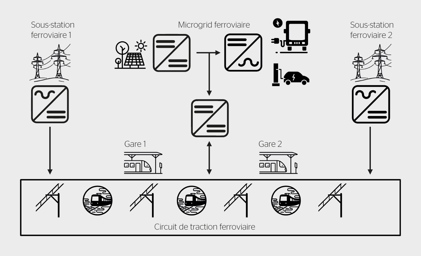
As mentioned above, the catenary experiences large voltage variations linked to the movement of trains. However, unlike trains, conventional energy production and/or storage systems, charging stations, or any other loads are designed to operate from a stable voltage source. The first technical point of this connection to the catenary therefore relies on the use of a specific converter that will stabilize the voltage of a DC bus, as illustrated in figure 2. This architecture corresponds exactly to a microgrid whose specificity is to allow energy flows between conventional electricity producers and consumers and the traction circuit.
Figure 2 General architecture of a railway microgrid for a direct-current network.
A second technical point is linked to electrical protection principles as specified in railway standards. The basic principle is based on detecting short-circuit faults on the line by the nearest substation. The latter is then responsible for isolating the fault, then automatically isolating neighboring substations to prevent the fault from being re-energized. Since safety must remain guaranteed, the connection converter of the railway microgrid to the catenary must be integrated into the line protection scheme similarly to the installation of a new substation. For faults occurring on the microgrid side, it is possible to specify galvanic isolation protection directly integrated into the converter.
Finally, the third technical point is about controlling energy flows between railway microgrids interconnected by the catenary. This control relies on an energy management system (EMS) that can meet the requirements of various monetizable services such as:
local energy production based on renewable sources;
integration of energy storage capacities;
the power supply necessary for charging electric vehicles in multimodal transport areas (more than 300 points in Switzerland);
exploitation of the railway network’s flexibility for system services;
and, finally, provision of backup power for emergency services in case of local power loss.
While these services are fully consistent with the energy context, the justification of the railway microgrid according to economic, environmental and societal criteria relies on valorizing land assets and railway infrastructure to contribute to the integration of renewable and local energy production. From an energy efficiency perspective, railway microgrids also help valorize train braking energy by powering electric vehicles parked near stations.
With the aim of developing this railway microgrid concept, the Smart Grid team of the Institute of Energy and Environment (IEE) at HES-SO Valais is developing simulation and energy management tools, the results of which are presented below.
Integration of a linear photovoltaic plant
The valorization of railway land is based on an architecture of a linear photovoltaic installation, that is, PV panels mounted side by side over a long distance along the track or between the rails (Sun-Ways solution). While current PV installation architectures perfectly meet the needs of conventional applications, it should be noted that they do not allow compliance with standards related to photovoltaic plants in the context of a linear PV installation longer than 1 km. The issues are based on the following elements:
"mismatch": the operating points of panels differ depending on irradiance variations and shading;
voltage drop: connecting PV panels via a DC bus is possible provided that the voltage variation is less than ±3% of the nominal voltage of the DC bus;
number of converters: connecting panels as a string via a single converter is required for economic and maintenance reasons.
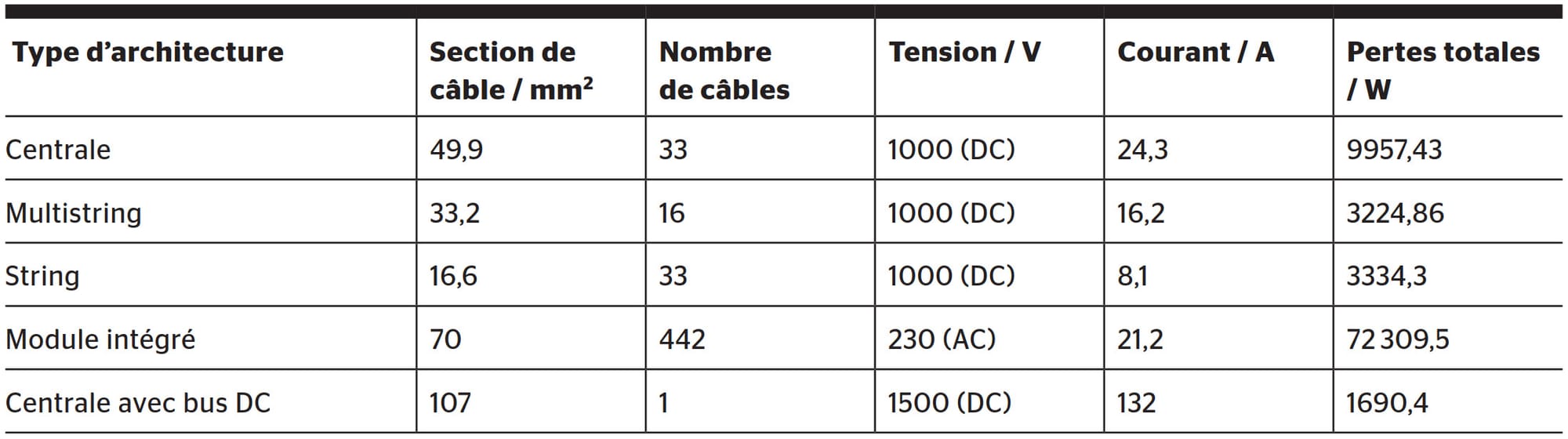
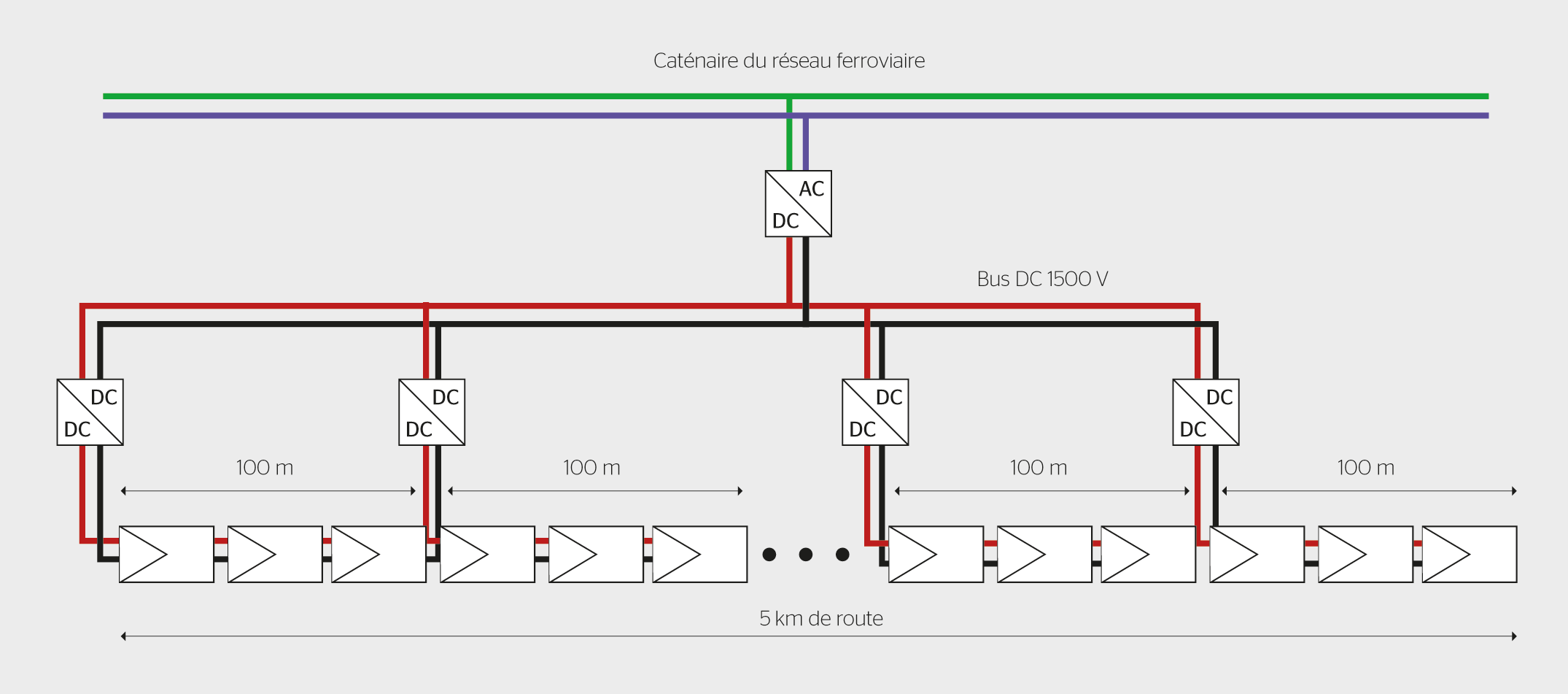
To meet these different constraints, a comparison of the possible associations led to selecting a central architecture with a 1.5 kV DC bus (table 2). This choice of voltage is linked to the objective of covering a distance of 5 km with an injection point in the middle (figure 3), that is, with two departures of 2.5 km each. With a view to extending distances while complying with the standard, it is appropriate to study the use of 3 kV DC buses (2 x 1.5 kV) or even 6 kV (2 x 3 kV).
Table 2 Comparison of different architectures for a linear photovoltaic installation along the track or between the rails with a length of 1.5 km.Figure 3 Architecture of a linear PV installation on railway land installed along the track or between the rails (Sun-Ways solution).
Based on this architecture, an application case was identified between Martigny and Vernayaz stations, on the Mont-Blanc Express line operated by TMR. This choice is explained by:
a 2.5 km section allowing the installation of a 400 kW linear PV plant between the rails or along the track;
the presence of TMR maintenance workshops in Vernayaz;
the presence of an energy storage system in the reversible substation of Vernayaz (figure 4).
Beyond this section, a more specific study of solar irradiance must be carried out to take into account production and the possibility of integration between the rails and/or along the track.
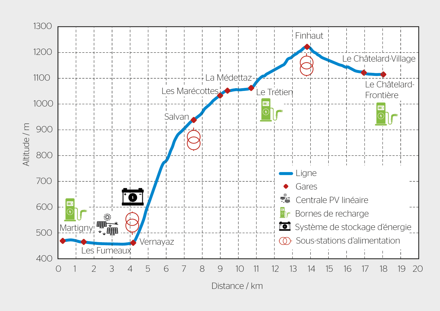
Figure 4 Profile of the Martigny – Le Châtelard railway line and position of railway microgrids for charging electric vehicles near stations.
For the chosen application case, results obtained based on an irradiance of 800 W/m2 indicate a reduction of 400 kW in the power drawn from the Vernayaz substation. In addition, in the absence of the storage system in the reversible Vernayaz substation, part of the trains' braking energy and photovoltaic production is pushed back onto the grid. This observation justifies integrating charging stations at the stations on the line, again as part of a railway microgrid approach.
EV charging via the railway microgrid
The objective of this microgrid function is, in a first step, to maximize the recovery of trains' braking energy by using it to charge electric vehicles parked near the stations on the Mont-Blanc Express line (see the line gradient in figure 4). In this case study, railway microgrids are deployed at the Martigny, Le Trétien and Le Châtelard-Frontière stations (figure 4). The use of public charging stations allows the implementation of V1G (smart charging according to available energy) and V2G (vehicle-to-grid, bidirectional charging) functions.
In order to guarantee the operation of the railway line – trains indeed automatically slow down if the catenary voltage is too low – the voltage plan was analyzed. This condition is necessary to validate the technical feasibility of this type of railway microgrid, insofar as it increases the load on the catenary.
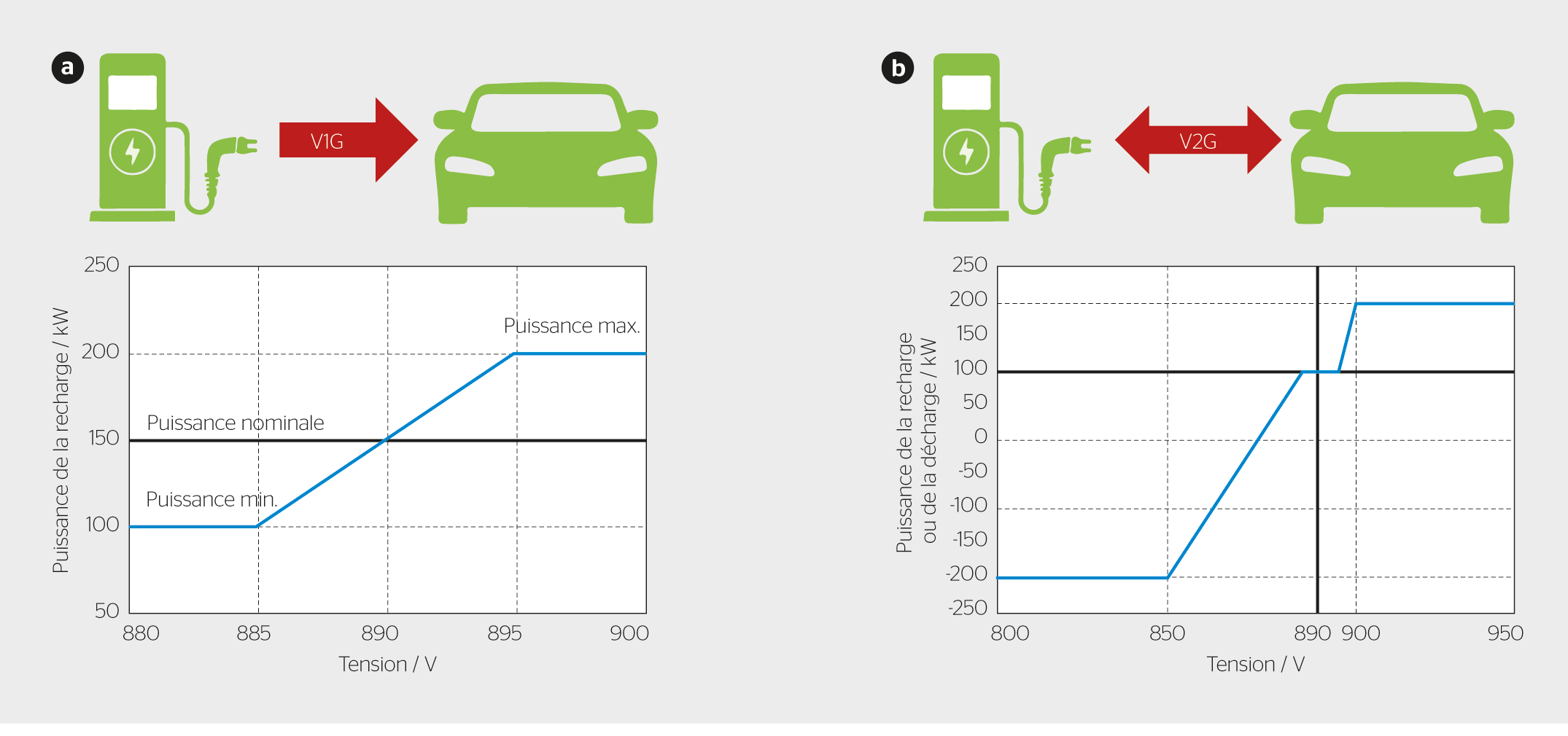
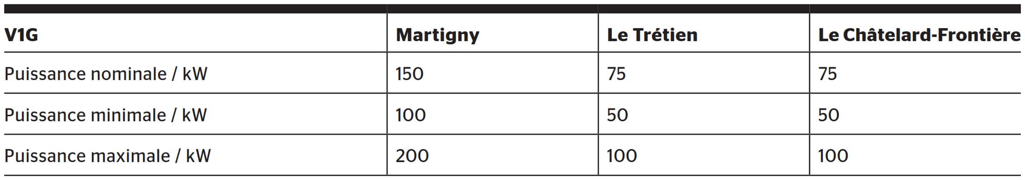
The objective is to manage EV charging according to the catenary voltage. A strategy based on "droop control" rules made it possible to adapt the energy management system to maximize the recovery of trains' braking energy (figure 5). Thus, if the voltage decreases, EV charging power is proportionally reduced. Conversely, if the voltage increases, charging power is increased, up to a saturation threshold (table 3). Following the same principle, the V2G function allows energy from EV batteries to be injected into the catenary to improve the voltage plan.
Figure 5 Configuration of the energy management system based on a "droop control" function: a) for smart charging (V1G), and b) for bidirectional charging (V2G).Table 3 Setting parameters of the "droop control" for smart charging (V1G).
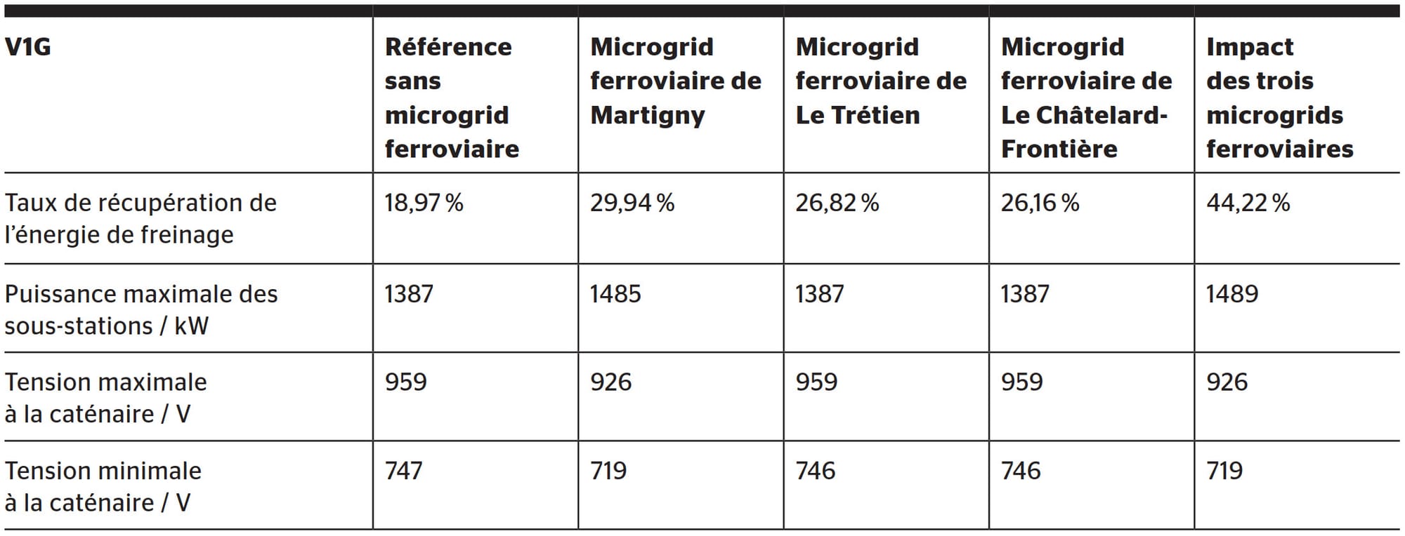
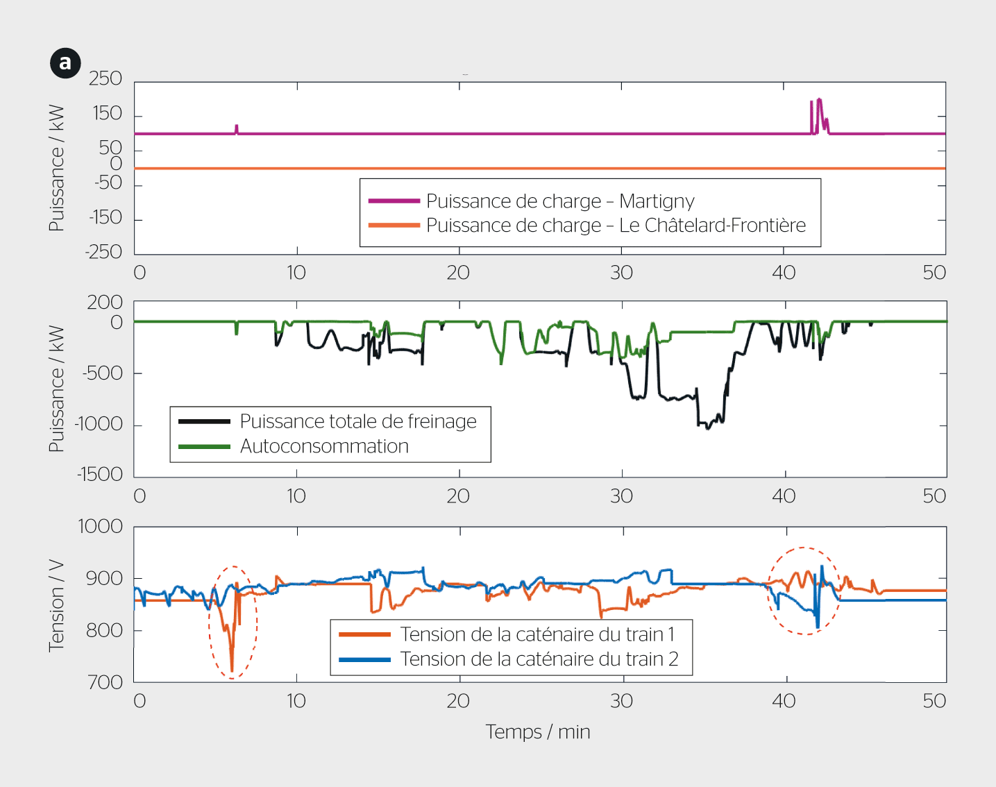
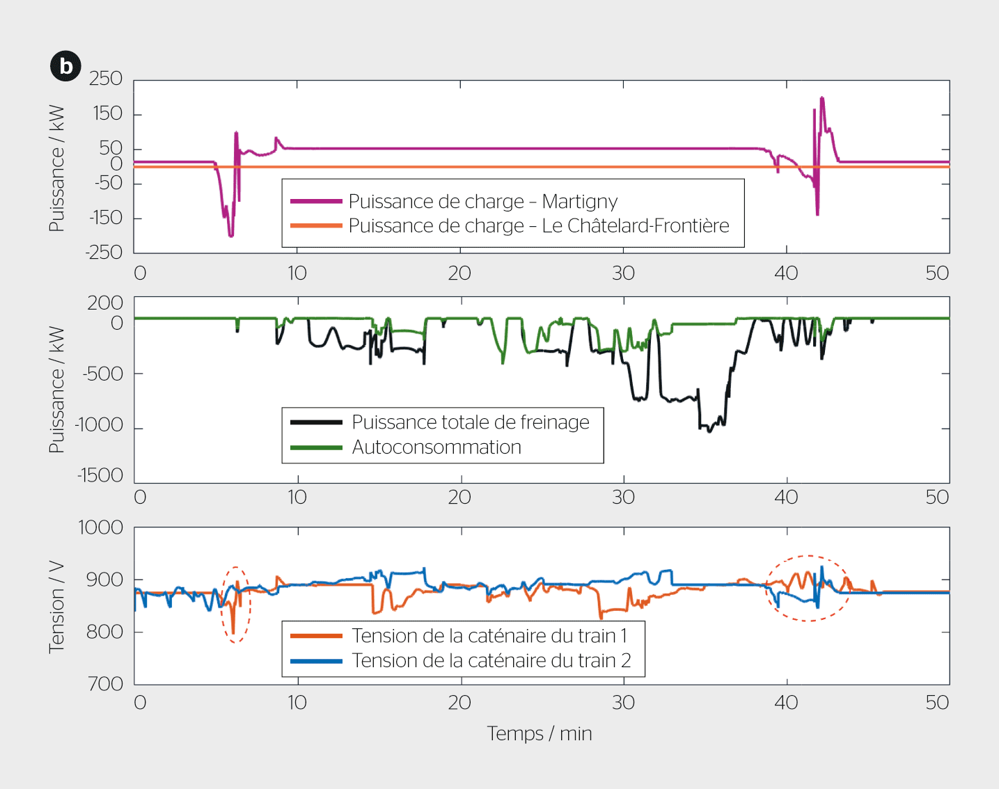
The study carried out using simulations of the line taking into account railway specifics made it possible to compare the impact on the line of each of the three railway microgrids compared to the reference case, that is, without a railway microgrid (table 4). To analyze the voltage seen by trains at the catenary, the PV linear plant microgrid was deactivated. Although voltage criteria conform to the standard – the catenary voltage remains well above the minimum threshold of 500 V (see table 4) – the V2G function was studied to assess its contribution to the railway system (figure 6). It should be noted that this function could also be carried out by discharging a stationary battery.
Table 4 Increase in the recovery rate of trains' braking energy thanks to the exploitation of railway microgrids.Figure 6 Comparison of the potential to stabilize the railway electrical network voltage using the Martigny station railway microgrid: a) with smart charging (V1G) and b) with bidirectional charging (V2G) of electric vehicles.
The obtained results highlight the interest of using the three railway microgrids to maximize the recovery of trains' braking energy, which thus reaches 44% instead of 19% for the reference situation. It should be noted that trains passing each other naturally recover part of the braking energy. For the railway system, the use of such microgrids also constitutes a solution to reinforce the catenary voltage plan, as shown in figure 6 for the Martigny area.
Conclusions and perspectives
With the aim of valorizing the Swiss railway electrical infrastructure, connecting a microgrid on railway land allows the integration of linear PV plants as well as charging stations for electric vehicles. The chosen architecture is based on a DC bus stabilized in voltage by a converter connected to the catenary. Safety functions are ensured by integrating the microgrid(s) into the protection scheme defined according to railway standards.
The areas available along the tracks can be exploited using a linear PV plant whose production is delivered to consumers via a 1500 V DC bus. In the Mont-Blanc Express application case, this production is partly self-consumed by the trains, and the surplus is injected into the energy storage system of the reversible Vernayaz substation. In the absence of an energy storage system, it is relevant to exploit this renewable and local energy to power one or more railway microgrids dedicated to charging electric vehicles parked near stations.
The results obtained with this case study demonstrated that the recovery rate of trains' braking energy could reach 44% – instead of 19% without railway microgrids – while guaranteeing the nominal voltage plan necessary for the operation of the railway line. They thus demonstrate the relevance of valorizing existing railway network infrastructures using microgrids.
To complete the technical and energy feasibility study, it is now necessary to establish the financial relevance of this solution. Previous projects integrating energy storage systems have shown a 30% reduction in investments, related to the valorization of existing electrical infrastructures (substation, MV connection, power line). Finally, an environmental study should evaluate the gains made by valorizing an existing asset such as a railway electrical infrastructure.
All these studies aim to lead to the implementation of a first railway microgrid based on a Swiss case study, either in DC (on a regional line), or in AC. In the latter case, the only necessary modification concerns the converter connected to the catenary. Finally, the microgrid portion planned for linear PV plants can also be integrated on road land, as envisaged by the Federal Office of Energy.
An analysis signed by:
Julien Pouget, professor at HES-SO Valais
Baoling Guo, scientific collaborator at HES-SO Valais
Thomas Meier, co-head of the Infrastructure department at Transports de Martigny et Régions SA
Joseph Scuderi, CEO of Sun-Ways
Frédéric Boisset, head of the electrical service at Sinergy
References:
Standard EN 50163 “Railway applications – Supply voltages of traction networks.”
What happens when insurance companies decide to withdraw and no longer cover the most at-risk areas? That is the theme at the heart of the new report by the environmental NGO, but also of "Sigma", that of the Swiss Re Institute. Analysis
"Flexibility solutions are now essential. However, they face a structural difficulty: their costs are decreasing faster than market rules evolve," explains Xavier Blot, associate professor at emlyon business school.
By naming their first edition "Wind farms are taking shape", the industry's players want to show a certain optimism despite a context that remains complicated for the sector. A look by Benoist Guillard, president of the Groupe romand pour l’énergie éolienne (GREE).
Since its founding in 2021, the young startup has made it its mission to find a good compromise between energy production and plant growth. The solution is called "spectral filtering".